Bart:
I enjoyed your article in QST. How far down from the top of the tower do you
recommend placing the rotator on my 30 foot tower?
Pete Bedrosian
W1WJG@aol.com
Pete:
It depends
on the tower construction mast length and the number of square feet of antenna
loading you will have. I have my rotor at the top most position with the
rotor plate on the first horizontal set of rungs down from the tower's
top. The mast length is 10 feet and, since my tower has a 6 inch
long mast sleeve that removes side to side loads from the
rotor incorporated in its design, I do not need a thrust bearing.
The mast extends 6 feet above the top of the tower.
Although I
can not give you a mathematical formula, I would consider the following when
making this decision:
1)
The length and construction of the mast: For masts longer then 15 to 20
feet, I would go to triple-wall construction. Also, consider that the
mast adds to the total wind loading and will subtract from the available wind
loading for the antennas. For example, if your tower is rated for 15
square feet of wind loading and you stack two antennas with 6 feet of loading
each, that will only allow 3 feet of wind loading for the mast. Wind
loading is the surface area exposed to the wind. If a mast is 2 1/2
inches in diameter (wide) and 10 feet long the wind loading is about 2 feet
(2.5" x 10'/12"). If you go to a 15 foot mast, you would be
right at the tower's specified limit without room for error. My advise
is to be conservative. A few extra feet will not make much difference in
performance.
2)
The wind loading of the antenna(s). Larger antennas or stacked
antennas require substantially more support.
3) If
you are going to have a tall mast or a big array, you will need a thrust
bearing. Within design limits, rotors handle vertical loads quite
well. They do not handle side to side loads efficiently, however.
A thrust bearing or a sleeve that is incorporated into the tower's design will
prevent overload damage to your rotor.
4)
The construction of your tower; i.e., light duty Vs. heavy duty construction.
I would not
try to push the envelope on height. Remember, you will need to be
able to have access to your antennas for repair. If the mast extends too
far above the top of the tower, you will not be able to strap yourself to the
mast, reach up and work on it as I do.
My final
word of advice is that you play it safe and not take chances. If you use
top quality materials including a double or triple wall mast as appropriate
and your final assembly looks balanced to the eye, you will probably be
ok. If it looks top heavy or unbalanced, it looks that way for a reason.
73,
Bart,
WB6WUW
P.S.:
If you enjoyed my article, please remember to vote for the article of the
month on the ARRL web site at . Thank you.
My
tower is already installed and is composed of 3 10-foot sections each weighing
35 LB for a total of 105 lb. It is mounted on a hinge and can be easily raised
and lowered with the winch that I already installed. I plan to use a 26.5
LB Cushcraft MA 5B Beam (Max wind surface area is 3.22 sq-ft) with a Hy-Gain
CD-45 II. Where do you recommend placing the Rotator and Max length of steel
mast? Is it possible to also mount a TV Antenna just above the top of the tower?
Thanks for any help.
Pete
You have
neglected to provide me important data. What is your
tower's maximum allowable wind load specification? Who is your
tower's manufacturer? Is it free standing or guyed? What is the
dimension on one side of the triangle?
Since your
ham antenna's wind load is comparable to that of a large TV antenna, I would
guess that you would have enough margin to stack a TV antenna, but I cannot
say for sure without knowing the towers maximum wind load specification.
Assuming your tower has either a mast sleeve or thrust bearing and you
use a 10 foot double wall mast, you should locate the rotor so no more then 6
or 7 feet of the mast protrudes above the tower's top plate. Please
understand that I am not an engineer and that these recommendations are not
based on the mathematical calculations an engineer would use to verify safety.
If you use
a 15 foot mast, you should consider triple wall construction. The
rotor would need to sit lower in the tower, so you will not gain 5 additional
feet over a 10 foot mast. I would limit the mast protrusion above the
top of the tower to 10 feet.
I really do
not have experience with 20 and 25 foot masts and am, therefore reluctant
to advise you. For that size mast, you should probably talk to someone
who has experience with large stacked arrays. If you really need that
height and you have a Rohm Tower such as their 45 series or a tower with a
similar modular design, you might be safer to add a section. If you do,
you must be sure that you do not exceed the design capabilities of your
footing.
73,
In
a message dated 6/19/03 9:23:06 PM Eastern Daylight Time, bart@wb6wuw.us
writes:
Hello again Bart:
Thanks very much for your reply. It is very helpful to me.
You have
neglected to provide me important data.
What is your
tower's maximum allowable wind load specification?
No Info on wind load
Who is your
tower's manufacturer?
American Tower (Popular Tower manufacturer for TV Antennas.)
Is it free
standing or guyed?
Free Standing
What is
the
dimension
on one side of the triangle?
12 inches (11-inch centers between each leg).
No Thrust bearing will be used, since it has a Mast Sleeve approx. 12 inches
long at the top. Do you lubricate the inside of your mast sleeve? I was planning
on placing a grease fitting in the sleeve. I can place the assembled Antenna and
Rotator at ground level as the hinged tower is supported by 6 foot support so as
to keep it off the ground in its "down position". The winch is a
few feet off the ground and is mounted on a 3-1/2 inch dia steel pole (cemented
in the ground behind the mast) that extends a couple of feet above the first
10-foot section where the pulley is attached. The tower is clamped to that pole
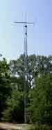
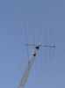
after it is in an upright position. Below is a picture of the erected tower. I
have also attached the photo.
73s
Pete (W1WJG@aol.com)
Hi Pete,
First Pete, I
want to preface this by saying that I have never worked with a TV type tower
and what follows is all guess work: i.e., I will not be held responsible if
everything comes crashing down. The fact that you are using a light
weight TV tower instead of a tower designed for ham or commercial use changes
everything. I find it disturbing that you do not have wind loading
specifications for your tower. That means you have no way of knowing if
you are exceeding design limits. I would contact American Tower and find
out the specifications and there recommendations and stay within that
envelope.
If you cannot
get that information, the safe thing to do is to assume that it was designed
for a small to medium size TV antenna and operate within those limits.
That means a 5 foot mast with the single ham antenna (no stacking with a TV
antenna) mounted no more then one or two feet above the top of the
tower.
If you insist
on pushing the envelope, you must consider these questions: What state
are you in? What are the highest wind gusts that have historically
occurred in your area; i.e. contact the U.S. Weather Service and ask
about the 100 year wind gust record for your area? Is your house
surrounded by large trees or other objects that provide a wind brake at tower
top height or are you in the open like a farm in Kansas? Also, did
you just dig a hole and pour in home mixed cement or did you build a footing
to the manufacturer's specifications? All of these factors must be
weighed in addition to those I mentioned in earlier e-mails.
As far as
lubrication of the mast sleeve, I like your idea of a grease fitting. I
wish I thought of that. I coated the inside of the sleeve on my tower
with high grade grease before insertion of the mast. When I do
maintenance that requires moving the mast up and then down again, I re-grease.
That means the sleeve gets greased only once in several years. I suspect
that one could get by with a dry sleeve since there is nothing to ware out in
that area and rotational motion is slow and infrequent. But, why take a
chance? I do think, however, that if you are using a light duty rotor,
that will be more of an issue since the friction with a dry sleeve will
present more of a torque load to the rotor. I use a Tailtwister that is
very overrated relative to the load I place on it, so that is not an
issue of concern.
73,
Bart
-----Original Message-----
From: Christian von Wechmar [mailto:christian@owf.co.za]
Sent: Monday, June 23, 2003 7:12 AM
To: bart@wb6wuw.us
Subject: FB QST Article
Hi Bart,
Great article in QST. I checked out your website too. My 40 foot crank-up tower is lying next to my house, waiting to be put up. Your article has
given me new courage, and many useful hints!
73 Chris ZS1DX
Hi Chris,
Thank you for your kind words. Believe it or not, I have not seen the July issue of QST yet. I have only seen the galley proofs of my article. Since they send QST by 4th class mail, California receives QST after the rest of the country. What is your QTH? Can you please tell me what pages they put it on and when you received it.
When you install your tower, could you please take lots of pictures and send me some? I would like to develop my website into a general resource with information from several tower installation projects from around the country. If you have any questions as you proceed, feel free to contact me and I will give you any aid I can.
73,
Bart, WB6WUW
Hi again Bart,
My QTH is Stellenbosch, near Cape Town, in South Africa! Glad to see that the international mail is faster than the local US mail HI.
Your article spans pages 33 to 37. I got my QST on Friday, 20 June.
I'll take lots of pics when I put it up. BTW, I voted for your article.
Good luck, and 73 de Chris ZS1DX
Great article in QST. I read every word. It is the very information that I
need. Last year or more I was given a Tri-Ex 36' tower. It
is a 36 footer. I plan on putting it up in my back yard in much like your
setup. I went to the city for permit information and was given the
guidelines that I would need to get the process approved. Now I am looking
for a set of blueprints of the hole, rebar etc. I have plans for my Plot
plans. I need the drawings for the hole and rebar. I was wondering if I
could use yours. I would be willing to pay a reasonable price for them. Is
this even possible?
Thanks in advance for any help and information.
Ed Genest
Oceanside, Ca
Thank you for
your kind words about my article. Tri-Ex, like all tower manufacturers,
has footing plans that are designed for your specific tower model. Using
the correct plan is important because a properly designed footing and
tower work together as a single unit to withstand loads. If you
were to use my plans, it is possible that they would be deficient in
three regards. First, depending upon your tower's design
specifications, it may or may not be adequate to withstand the load.
Secondly, if the city engineer notices that the plans specifically identifies
a manufacturer other then Tri-Ex, your permit will not be approved.
Finally, the certification on my plans states that the calculations are based
on the 1985 UBC. If Oceanside's Department of Building and Safety's
rules are like Buena Park's, they will insist that the specifications be
recalculated by a certified engineer to the most recent UBC (1997).
Therefore, the most logical course of action is to procure plans from the
manufacturer.
Tri-Ex was
bought out by Tashjian Towers Corporation. There address is 2183 South
Highland Avenue, Sanger, CA 93657. Phone: (559) 495-0307.
There URL is http://www.karltashjian.com.
If you have
any other questions, please feel free to contact me.
73,
Bart, WB6WUW
-----Original
Message-----
From:
demarco@usp.br [mailto:demarco@usp.br]
Sent:
Saturday, June 28, 2003 9:46 AM
To:
bart@wb6wuw.us
Subject:
QST tower article
Hello
Bart,
I
want to thank for your article on QST. I have a crank-up tower lying on the
garden floor, guess that it was an article like yours I was waiting for!
Indeed
I voted for it on the ARRL web site.
My
tower is self supporting and consists of two sections, 26 feet each, with a
hinged base.
I'd
like to know some more details about the foundation and rebar cage in order
to compare with mine. What are the diameters of the steel used on the rebar
cage? How many horizontal and vertical sections comprise the cage?
73,
Joao
Kolar De Marco, PY2FCE
in
Atibaia, São Paulo, Brazil
Hi Joao,
Thank
you for the kind words and your vote.
Without
pulling out the file, I do not remember the rebar diameter. As I recall,
the specifications are four vertical on each of the four faces of the rectangle
and one horizontal member spaced 6 inches apart with 4 inch spacing between the
top and bottom most members. The length of all sides was such that there
is a 6 inch clearance between the cage and the vertical faces of the hole and 4
inches between the bottom and top of the concrete. You should not use this
as a specification for your footing however, since you have a different tower
design. You must go according to the tower manufacturer's recommendations
and your local building code to ensure safety.
73,
Bart,
WB6WUW
-----Original
Message-----
From:
WA4AIP@aol.com [mailto:WA4AIP@aol.com]
Sent:
Friday, June 27, 2003 8:55 PM
To:
bart@wb6wuw.us
Subject:
QST tower article
Bart,
I
thoroughly enjoyed your article in the July issue of QST. I
have the "base" poured and ready for a US Tower TMM-433SS later this
summer. Would
you please clarify a couple of terms you used in your article for me; "drift pin" and "ground rod box?"
I
am not familiar with these two terms!
Additionally,
being in Florida, I am interested in a "quick disconnect" method at
the tower base to isolate the RG-213 running from the antenna into the shack
some 125' away -- my concern is lightning strikes!
Your
assistance on these items will be greatly appreciated, Bart.
73,
John
WA4AIP
Hi John,
Thank you for
your e-mail. If you liked my article, please vote in the monthly QST
contest at http://www.arrl.org/members-only/qstvote.html?pidx=0.
A
"drift pin" or "bull pin" is basically a tapered steel rod
that you jam into an adjacent hole set to force the holes through which you need
to place a bolt into alignment.
I
used the term "ground rod box" to describe an area surrounded by
concrete where you can drive ground rods. As I mentioned in the article,
the tower footing is part of an extension to my pool deck. Since the
concert deck now goes right up to the house, it was necessary to have an area on
the outside wall of the house directly opposite the placement of the rig for the
station and tower ground. This allows ground strap from my rig to the
ground to be under 6 feet. The tower's center is about 2 feet from the
ground box and it is grounded with a 2 1/2 foot length of number 2 welding
cable.
As
far as lightning protection goes, I am not an expert on that subject. We
seldom have lightning in Orange County, California, so the only protection I
really need is the arrester built into my tuner. On the few occasions we
have static activity, I disconnect the coax as a precaution, but I am not aware
of anyone in the area who has ever suffered damage.
As
far as quick disconnects go, I have a quick disconnect PL259 that I use to
connect my 2 meter HT to an outside antenna. The trade off is that is a
little more inefficient then the standard screw on type. In any case, I
would talk to your local hams about lightning issues since they probably have
experience.
73,
Bart, WB6WUW
-----Original
Message-----
From: Larry R. Ragland [mailto:ragland@teleport.com]
Sent: Thursday, June 26, 2003 5:34 PM
To: bart@wb6wuw.us
Subject: QST Article, ISO 9000
Hi
Bart,
I
appreciated your article in the July QST. Good job. I
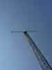
have one question. In
Figure 7, is the gray line running from the top of the gin pole to the bottom
left corner of the photo the rope used to pull the antenna to the top of the
tower? If
so, my suggestion would be to first run this rope to a block very near the base
of the tower. Then, the tower tension load is nearly straight down,
instead of putting a horizontal load component at the top of the gin pole.
73,
Larry
Ragland, W7LRR
Hi
Larry,
Thank
you for the e-mail. You are correct. The line is going through the
pulley. On the left and out of the picture, someone is holding the rope
that is supporting the beam.
I
agree whole heartedly with your suggestion about running the rope down the
tower.
If
you liked the article, please vote in the QST monthly contest at http://www.arrl.org/members-only/qstvote.html?pidx=0.
73,
Bart,
WB6WUW
-----
Original Message -----
To:
bart@thouse.com
Sent:
Thursday, June 26, 2003 6:03 PM
Subject:
QST
Hello
Bart.
I
just finished reading your article in QST on tower/antenna. I
am in the process of re-installing my tower/antenna at my new QTH. Am
always looking for time-saving methods for doing things like this.
Very
good article, but I felt you missed two important steps. There
was no mention of the leveling nuts under the tower baseplate.
On
my first installation, I did not install these little items, which makes
for
a real leveling pain. There was know mention of leveling the tower
at
all. Its very important that the tower is not leaning after its erected.
There
was also know mention of aligning the rotor with the thrust bearing.
This
is also very important. Im still trying to find a simple way, short of
shims
of doing this.
On
past installations I have made every mistake possible. If I had your article
in the past I would have made way fewer mistakes. This
installation I'm doing now, US Tower has changed the specs. on
the hole & cage. I have the TX-455 tower. It
now requires a 5X5X6 ft. hole, and about a 300# rebar cage. A
backhoe did this in about 30 minutes. The backhoe operator
was
not real careful and the sides were not straight. Instead of 6
yards of cement, it took almost 8 yards. I had ordered 7 yards.
The
driver was very quick at getting me another yard at about
three
times the cost of the other 7 yards.
I
rented a cement vibrator for $50. It really was worth it. You never realize
how
much air is trapped in the cement during the pour.
Again
your article was very good and would save a lot of time and
mistakes
for a first-timer. I
got my ticket in 1954. Am still in the learning process.
73
& good DX
Ron
K6JAH
Thank you
for the kind words about my article. You are absolutely correct about
the leveling screws and alignment. I never even realized I forgot about
it until I received your e-mail. As far as the rotor alignment, the
editor cut that. I wrote the piece as a two part article, expecting it
to be published in two successive issues. The first part covered the
footing and the second the tower and antenna raising. The editor decided
to combine it into a single article, so about half of my original text was
deleted. Although I reviewed the galley proofs, I recognized that some
things had to go to make it fit. I think the editor cut the rotor
alignment because it is usually covered in the rotor's instruction book.
It is
interesting about US Tower's increased footing specifications. I would
guess this may be due to the 1997 revision of the UBC. The code is
revised approximately every ten years.
73,
Bart,
WB6WUW
-----Original
Message-----
From:
WA4AIP@aol.com [mailto:WA4AIP@aol.com]
Sent:
Friday, June 27, 2003 8:55 PM
To:
bart@wb6wuw.us
Subject:
QST tower article
Bart,
I
thoroughly enjoyed your article in the July issue of QST. I
have the "base" poured and ready for a US Tower TMM-433SS later this
summer. Would
you please clarify a couple of terms you used in your article for me; "drift pin" and "ground rod box?"
I
am not familiar with these two terms!
Additionally,
being in Florida, I am interested in a "quick disconnect"
method
at the tower base to isolate the RG-213 running from the antenna into
the
shack some 125' away -- my concern is lightning strikes!
Your
assistance on these items will be greatly appreciated,
Bart.
73,
John,
WA4AIP
BART,
THANK YOU FOR YOUR PROMPT REPLY TO MY EMAIL! SEE
CAP NOTES BELOW:
Hi
John,
Thank
you for your e-mail. A
"drift pin" or "bull pin" is basically a tapered steel rod
that you jam
into
an adjacent hole set to force the holes through which you need to place
a
bolt into alignment.
UNDERSTOOD. THE CONTRACTOR DID NOT GET MY BOLTS TOTALLY
VERTICAL SO I WILL PROBABLY NEED A LITTLE LEVERAGE IN ORDER TO SLIP THE TOWER BASE ON THE BOLTS!
I
used the term "ground rod box" to describe an area surrounded by
concrete
where
you can drive ground rods. As I mentioned in the article, the tower
footing
is part of an extension to my pool deck. Since the concert deck now
goes
right up to the house, it was necessary to have an area on the outside
wall
of the house directly opposite the placement of the rig for the station
and
tower ground. This allows ground strap from my rig to the ground to be
under
6 feet. The tower's center is about 2 feet from the ground box and it
is
grounded with a 2 1/2 foot length of number 2 welding cable.
NEVER
THOUGHT OF WELDING CABLE. I WAS PLANNING TO RUN A COUPLE OF COPPER STRAPS TO 1" COPPER PIPES 8' IN THE
GROUND.
As
far as lightning protection goes, I am not an expert on that subject. We
seldom
have lightning in Orange County, California, so the only protection I
really
need is the arrester built into my tuner. On the few occasions we
have
static activity, I disconnect the coax as a precaution, but I am not
aware
of anyone in the area who has ever suffered damage.
As
far as quick disconnects go, I have a quick disconnect PL259 that I use
to
connect my 2 meter HT to an outside antenna. The trade off is that is a little
more inefficient then the standard screw on type. In any case, I
would
talk to your local hams about lightning issues since they probably
have
experience.
I
HAVE BEEN TO ORANGE COUNTY MANY TIMES DURING MY CORPORATE YEARS OF NATIONAL TRAVEL! THE ONLY WAY TO TRULY
PREVENT LIGHTING FROM ANTENNA TO COAX TO RIG IS TO DISCONNECT THE COAX! I AM LOOKING FOR OR WILL FABRICATE A
PLASTIC BOX TO USE AS A DISCONNECT POINT IN THE CABLE RUN. YOU ARE EXACTLY RIGHT, THE CONNECTION DOES COST YOU SOME
EFFICIENCY IN POWER.
THANK YOU AGAIN FOR YOUR RESPONSE, BART.
GD LUCK AND 73 JOHN
Hi
John,
If
the hyperlink doesn't work, go to the ARRL Members Only Page. There is a
hyperlink just above the buff colored FAQ section, "Vote for the best July
2003 or June 2003 QST story!"
I
wouldn't have thought of the welding cable myself if I had not worked for a
company that made welding robots at the time. The welding cable I use is
rated for 8 KW. Only a direct or near direct hit could cause it to open.
In addition, it is copper stranded so it is flexible and the insulation is a
thick rubber like material, so it handles the environment very well.
73,
Bart,
WB6WUW
-----Original
Message-----
From: Thomas Cordich [mailto:wb6lpn@worldnet.att.net]
Sent: Monday, June 30, 2003 10:59 AM
To: bart@wb6wuw.us
Subject: your QST article
I
read your article on tower and antenna installation
and
found it very interesting although as a old ham with
a "do it yourself " mentality I found a few things I
might reflect on. I have installed 6 tower and antenna
installations
in 2 states so I do have some practical
experience.
First
if you are not aware, US Tower and its former
company
names ( Tristao, and Palmer ) have, since the
1960's offered on loan or for sale, tower raising fixtures
and dollys so the need to make or use home made
devises is not needed. It also precludes the
need
for more than two people to do an entire install.
Second,
the antenna , rotor, mast, coax and all items
can
be installed from ground level and as a matter of
fact
US Tower does not endorse or encourage the
climbing
their towers for any reason. If anything they
highly
discourage the climbing of their towers. All
raising and lowering fixtures can be rented or bought
at any time.
Third
item of interest or info is the respective
building
departments have soil information and the
need
for a civil engineer is fine if you want to spend
extra
money but the building departments will usually
tell
you what is needed for hole size and cement
configuration
as needed for the soil content in their particular
area.
As
an added point, most professional builders that
I
have worked with will not weld the basket but will
instead
wire it together. I am not sure why but am told
it is more permanent as a weld could separate.
The
last comment I have is one I am in total agreement
with
you on and that is the waiting of a period of time before
installing the antenna or coax as I have had the same
experience and was smiling when I informed and
was
able to show the complainant that there was nothing connected
from the tower to the radio. That advise was
given
to me in the 1960's by another ham who seemed
to
know that people will complain for no true reason.
Nice
article and if you were not aware of the items and
info
I am sending - this is what ham radio is about - and
that
is sharing information with each other.
73
Tom w7tc
Hi
Tom,
Thank
you for your e-mail. Since your raised several issues, I will answer them
in order.
1)
Although I am aware that Tristao, Tristao and Pratt and US Tower have offered
tower raising fixtures for sale, I was not aware of a rental or loan policy.
In my particular installation, use of both the tower raising fixture and on
ground antenna installation was precluded by the fact that there is a 6
foot high cinderblock wall on the far side of the swimming pool over which the
tower had to be laid before erecting. In order to have space on my
property, a tower leg needed to be placed 6 inches from the outside wall of the
house. With the tower laying across the pool and the base attached with
the hinge bolts, the top of the tower in the full down position was 5 inches
from the wall.
2)
Just about all tower manufactures publish written statements discourage climbing
towers to protect themselves from law suits. I agree with you that
climbing should be avoided if possible, but it is not always possible.
3)
I didn't hire a structural engineer by choice. Since the tower was
constructed according to the 1975 UBC, the City of Buena Park, California
required me to have the tower and footing specifications re-certified to the
1985 UBC. At the time I bought my tower, Tristao and Pratt were in
financial trouble (I didn't know that when I place my order). As a result,
Lou Tristao built my TX 438 tower from the lower two sections of a TX 455.
I didn't argue with him at the time, since I got a tower with an 18 inch lower
section and 15 1/2 inch upper section, rather then the 15 1/2 and 12 inch
sections that the standard TX 438 specification called for.
Effectively, I got what is now the TX 535 for the same price as a TX 435 (Tristao
and Pratt did not make a heavy duty 38 foot tower at that time). When I
moved to Buena Bark, the Department of Building and Safety was not impressed
that the footing specification was for a 55 foot tower rather then the 38 foot
tower I had and would not issue the permit without re-certification.
4)
The rebar cage at the first location was wired. The contractor for my
current location welded the cage. I was not even aware that you could weld
a rebar cage until I saw it. He said it was more reliable. Frankly,
I don't know. On the one hand, a properly made weld is as strong as the
original material. Please understand that my welding expertise in that
regard is confined to TIG welding of stainless steel and titanium. On
the other hand, it also makes sense that wiring the rebar would allow some
slight movement that might be beneficial.
5)
I waited to put up the antenna because I had seen the same advice in QST
in the 60's and had also heard similar stories from other hams over the years.
If
you enjoyed my article, please vote in the QST cover award
competition at http://www.arrl.org/members-only/qstvote.html?pidx=0.
If you have trouble with that hyperlink, you will find a link on the members
only page on the ARRL web site.
73,
Bart, WB6WUW
Sounds
like you had a terrible time and place
of
installation. My condolences ! I have always
tried
to survey the place I am going to live to
prevent
problems such as you encountered. I
have a 1 1/2 acre place here in Nevada with
no
restrictions, so along with my tower and beams
for 10 thru 20 and a 40 meter mono-bander,
I also have a Hy-tower vertical and a
256
foot horizontal loop. Great setup for DX
or
anything else. Great article too and glad
your
tower and beam work well for you. I guess
some of us are lucky. By the way, my
sister-in-law
lives in Buena Park! I sure hope
she
was not the neighbor who complained.
HI
HI 73 again Tom w7tc
I
surveyed
the area too, but in Southern California, even most million dollar homes
don't have 1 1/2 acre lots. Most of the average homes in Orange
County (the average price is $390,000), have only six feet on either side to the
property line. I did write a clause in my offer to buy to allow me to
cancel the deal if there were any CC&R's restricting antennas.
Luckily, there were none.
I
would love a Hy-tower for 40 and 80, but since my wife won't let me put one in
the front yard, there is no place to put it! The longest antenna I can fit
is an inverted-v on 40. I would like to convert my KT34A to a KT34XA, but
it is too big. When I point my KT34A north to south, it is within my
property line. At a 45 degree heading the elements overhang my neighbor's
property. If I upgraded to an XA, I could not position it so that it would
not overhang. This is not an issue with my current neighbor, but if he
were to sell his house, I could be in a bad position. In the end, I think
I have done all I can with the available space restrictions. I am,
however, very open to suggestions!
I
never found out for sure who complained because the city inspector said it was
confidential. However, I think it was one of two people and they have
both moved.
Thank
you for voting.
73,
Bart,
WB6WUW
I
have no suggestions but you do have my sympathy. I used to live in Lakewood Cal.
and that city was very cooperative but that was a long time ago. I had both
a 72-foot tower and a Hy-tower there with a tri band and a 40-meter beam. I have
always tried to have stacked beams at my QTH. I do understand your plight as I
have been there.
The
best 2 cities in So. Ca. were Lakewood and Bellflower but who knows about now a
days. The good times may be gone in Ca. I do realize that it is much more
congested there than when I was a resident. I did have the lot size problems
that you had. In Lakewood I had just enough room for the tower to tilt up and
after clearing the rear fence I could install the mast and antenna's. My
tower cleared the rear fence by 2 feet before
it was tilted up. I was lucky.
Tom w7tc
My
question is more about an observation. Was the antenna installed a KT34?
It is funny but I just ordered my tower last Thursday and your article, neat
by the way, was very timely. Getting published in QST, I am a life
member, had to be a highlight of your ham career. I would like to get
some info on the rebar arrangement. How did you determine how much
concrete you would need? I am using the Rohn 40 inch short base in the
concrete so if I move I just leave the short base. I am then going up 4
-10 foot sections and a flat-top, top section that is 8 foot with a TB-3
in it. I am using a 36 inch house bracket, up 6 feet. Thank you for
your time.
Regards
73
Conrad
Nasatka
The
antenna is a KLM KT34A and, yes; getting published is a highlight.
The
rebar specifications should come from your tower's manufacturer. If you
are buying a new tower and the manufacturer will not provide all
specifications certified to the latest UBC, I would not buy that
manufacturer's product. Those documents will include the minimum
requirements for the concrete mix. It is ok to exceed that spec, but do
not go below it. If you live in a municipality, your local building code
may also require minor modifications to the manufacturer's drawings. For
example, closer horizontal member spacing or thicker rebar, concrete
specifications, etc. Since each tower design is unique, the
specifications for my tower's footing would not be applicable to yours.
Which
Rohm tower are you considering? Is it free standing or guyed?
Although I have no experience in the matter, I have been told that bracing the
tower against the house can conduct noise from wind induced tower
vibration into the structure. You should check that out before you
proceed and let me know what you find.
As
you can see on my website, www.wb6wuw.com,
I have been compiling e-mails such as yours as a resource for other hams
considering a tower. I would appreciate it if you would take photographs
and send me copies in .jpg or .gif format for posting as you proceed with
construction. Thank you.
----- Original Message -----
Sent: Wednesday, July 09, 2003 9:31 PM
Subject: tower rerference material
Dear
Bart:
Read
your timely article in QST with great interest. I recently moved to
an area with no antenna restrictions. As a result, I am erecting a
tower. I am unfamiliar with the term "ground box" and
quite frankly, am in need of additional reference material on the subject
of installing a tower, proper grounding, etc. Are you aware of such
a reference? Enjoyed your article greatly and look forward to your
reply.
Vy
73 and congratulations on your publication!
Ty
KC4NWF
(Russell
T. Garland, M.D.)
You
are the second person to ask that question. "Ground rod box"
is a descriptive term I dreamed up for lack of any better terminology.
Since I needed to drive my ground rods in an area that would be within the
boundaries of my pool deck extension, I framed a one-foot square around which
the concrete was poured. This left a one-foot square area uncovered by
concrete where I could drive my ground rods. On one side of the framed
box, I ran a 1 inch diameter PVC pipe under the concrete to an area that
would be clear of the pool deck. This conduit was used to run a drip
irrigation hose to the ground rod box. The soil is kept damp by the drip
hose to increase ground conductance. I chose a flow device that drips
about one gallon of water an hour. I ran a second 2 inch diameter PVC
pipe under the concrete from the other end of the box to act as a conduit
for a number 00 welding cable to ground the tower.
If
you want more detail then QST published in the edited for space article,
please go to my website at www.wb6wuw.com
and click on the picture of my tower at the top of the page. One of the
reasons I wrote the article was because I could not find a similar article in
my 30 year collection of QST Magazines. As far as grounding schemes, I
would look at past issues of QST, 73 and the ARRL Handbook.
Basically,
you need two grounds. First a station ground for your equipment.
The ground rod should be as close to the equipment as possible. For high
frequency, if the ground is too long it can act like an antenna and cause TVI.
Since I positioned my ground rod near the wall opposite my rig, I was able to
ground my station with a 4-foot ground strap. If you must run a long
ground wire as I did when I lived in a second story apartment, you will need a
choke in the ground wire. Since a long ground wire has resistance (all
it takes is a few ohms), your rig will be at some point above ground.
For high frequencies, the ground wire can radiate and cause TVI. A
properly designed choke will attenuate the radiation.
The
second ground is for the tower. Since we do not have lightning problems
in costal Southern California, my tower is directly grounded through a 3-foot
welding cable. Since, judging by your call sign you must consider
lightning or high energy static discharges, you will need a lightning
arrester. You will find allot of information on that subject in QST,
73 and the ARRL Handbook. You should use a common point ground (the
same ground rod for both grounds) if physically possible. This will
prevent the possibility of ground loops.
Thank
you.
Bart,
WB6WUW
Dear
Bart:
Thank
you for the very kind reply. I know that it took you a long time to
compose that!! The information that you supplied is exactly what I need.
I will click on the ARRL site tonight. You've got my vote! Wish I could
vote more than once, but I'm not in Alabama or Mississippi. Shack will be on
third floor of my house in the theater room. I used RFI isolators supplied by
Radio Works coupled to a #1 AWG cable, 1" braid tying everything to
a common point with multiple Alpha Delta lightning arrestors. I grounded
every antenna when not in use.
I'll
check your website. I ordered the ARRL Antenna book last night .
Good luck, TNX, and hope to see you down the log!
Vy
73
Ty
KC4NWF
For more how to information about tower installation
visit www.ko4bb.com.
Last updated December 7, 2003